
High Quality, Low Price, Express Delivery Worldwide
Polymers
Polymers and plastics are used in nearly every industry and everyday life. Natural and synthetic polymers can be produced with a wide range of stiffness, strength, heat resistance, density, and even price. Macromolecular science has had a major impact on the way we live. It is difficult to find an aspect of our lives that is not affected by polymers. Just 50 years ago, materials we now take for granted were non-existent. With further advances in the understanding of polymers, and with new applications being researched, Polymers is an important sector of Chemicals.
Classes of Polymers
Polymer science is a broad field that includes many types of materials which incorporate long chain structure of many repeat units. The two major polymer classes are :
Elastomers,or rubbery materials, have a loose cross-linked structure. Typically, about 1 in 100 molecules are cross-linked on average. When the average number of cross-links rises to about 1 in 30 the material becomes more rigid and brittle. Natural and synthetic rubbers are both common examples of elastomers.
Plastics are polymers which, under appropriate conditions of temperature and pressure, can be molded or shaped (such as blowing to form a film). In contrast to elastomers, plastics have a greater stiffness and lack reversible elasticity. All plastics are polymers but not all polymers are plastics. Some plastics, such as nylon and cellulose acetate, are formed into fibers. Some of the main chain polymer liquid crystals also are the constituents of important fibers. Every day plastics such as polyethylene and polyvinyl chloride have replaced traditional materials like paper and copper for a wide variety of applications.
Polymer Glass Transition (Tg ) and Mechanical Properties
For polymers and their applications, it is important to understand the concept of the glass transition temperature, Tg. As the temperature of a polymer drops below Tg, it behaves in an increasingly brittle manner. As the temperature rises above the Tg, the polymer becomes more rubber-like. Thus, knowledge of Tg is essential in the selection of materials for various applications. In general, values of Tg well below room temperature define the domain of elastomers and values above room temperature define rigid, structural polymers.
Another important property of polymers, also strongly dependent on their temperatures, is their response to the application of a force, as indicated by two main types of behavior: elastic and plastic. Elastic materials will return to their original shape once the force is removed. Plastic materials will not regain their shape. In plastic materials, flow is occurring, much like a highly viscous liquid. Most materials demonstrate a combination of elastic and plastic behavior, showing plastic behavior after the elastic limit has been exceeded.
Glass is one of the few completely elastic materials while it is below its Tg. It will remain elastic until it reaches its breaking point. The Tg of glass occurs between 510o- 560o C. In comparison, polyvinyl chloride (PVC) has a Tg of 83o C, making it good for cold water pipes, but unsuitable for hot water. PVC also will always be a brittle solid at room temperature.
Adding a small amount of plasticizer to PVC can lower the Tg to – 40o C. This addition renders the PVC a soft, flexible material at room temperature, ideal for applications such as garden hoses. A plasticized PVC hose can, however, become stiff and brittle in winter. In this case, as in any other, the relation of the Tg to the ambient temperature is what determines the choice of a given material in a particular application.
A further complication arises in dealing with general polymers from their semi-crystalline morphology in which amorphous regions and crystalline regions are intermingled. This gives rise to a mixed behavior depending on the percent crystallinity and on their temperature, relative to Tg of the amorphous regions. The inhomogeneity of the material and its characteristics presents interesting analytical challenge
Applications of Polymers
These are by no means all of the applications, but jist a cross section of the ways polymers are used in industry.
Elastomers:
Rubber is the most important of all elastomers.
Natural rubber is a polymer whose repeating unit is isoprene. This
material, obtained from the bark of the rubber tree, has been used by
humans for many centuries. It was not until 1823, however, that rubber
became the valuable material we know today. In that year, Charles Goodyear
succeeded in "vulcanizing" natural rubber by heating it with
sulfur. In this process, sulfur chain fragments attack the polymer chains
and lead to cross-linking.
The term vulcanization is often used now to describe the cross-linking of
all elastomers.
Much of the rubber used in the United States today is a synthetic variety called styrene-butadiene rubber (SBR). Researchers eventually found success using butadiene and styrene with sodium metal as the initiator. This rubber was called Buna-S -- "Bu" from butadiene, "na" from the symbol for sodium, and "S" from styrene. During World War II, hundreds of thousands of tons of synthetic rubber were produced in government controlled factories. After the war, private industry took over and changed the name to styrene-butadiene rubber. Today, the United States consumes million tons of SBR each year.
Plastics:
Americans consume approximately 60 billion pounds of
plastics each year. The two main types of plastics are
Thermoplastics - soften on heating and harden
on cooling.
Thermosets, on heating, flow and cross-link to form rigid material
which does not soften on future heating.
Thermoplastics account for the majority of commercial usage. Among the
most important and versatile of the hundreds of commercial plastics is
polyethylene. Polyethylene is used in a wide
variety of applications because, based on its structure, it can be
produced in many different forms. The first type to be commercially
exploited was called low density polyethylene (LDPE)
or branched polyethylene. This polymer
is characterized by a large degree of branching, forcing the molecules to
be packed rather loosely forming a low density material. LDPE is soft and
pliable and has applications ranging from plastic bags, containers,
textiles, and electrical insulation, to coatings for packaging materials.
Another form of polyethylene differing from LDPE only in structure is high
density polyethylene (HDPE) or linear
polyethylene. This form demonstrates little or no branching,
enabling the molecules to be tightly packed. HDPE is much more rigid than
branched polyethylene and is used in applications where rigidity is
important. Major uses of HDPE are plastic tubing, bottles, and bottle
caps.
Other forms of this material include high and
ultra-high molecular weight polyethylenes. HMW and UHMW,
as they are known. These are used in applications where extremely tough
and resilient materials are needed.
Fibers:
Natural fibers such as cotton, wool, and silk have been
used by humans for many centuries. In 1885, artificial silk was patented
and launched the modern fiber industry. Man-made fibers include materials
such as nylon, polyester, rayon, and acrylic. The combination of strength,
weight, and durability have made these materials very important in modern
industry.
Generally speaking, fibers are at least 100 times longer than they are wide. Typical natural and artificial fibers can have axial ratios (ratio of length to diameter) of 3000 or more.
Synthetic polymers have been developed that posses desirable characteristics, such as a high softening point to allow for ironing, high tensile strength, adequate stiffness, and desirable fabric qualities. These polymers are then formed into fibers with various characteristics.
Nylon (a generic term for polyamides) was developed in the 1930's and used for parachutes in World War II. This synthetic fiber, known for its strength, elasticity, toughness, and resistance to abrasion, has commercial applications including clothing and carpeting. Nylon has special properties which distinguish it from other materials. One such property is the elasticity. Nylon is very elastic, however after elastic limit has been exceeded the material will not return to its original shape. Like other synthetic fibers, Nylon has a large electrical resistance. This is the cause for the build-up of static charges in some articles of clothing and carpets.
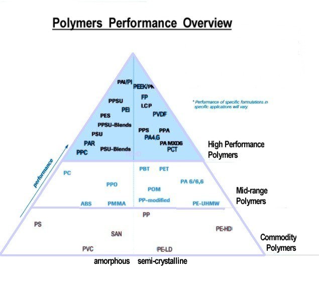
Relative Performance of Plastics:
Processing Polymers
Injection molding and extrusion are widely used to process plastics while Spinning is the process used to produce fibers.
Injection Molding:
One of the most widely used forms of plastic processing is
injection molding. Basically, a plastic is heated above its glass
transition temperature (enough so that it will flow) and then is forced
under high pressure to fill the contents of a mold. The molten plastic in
usually "squeezed" into the mold by a ram or a reciprocating
screw. The plastic is allowed to cool and is then removed from the mold in
its final form. The advantage of injection molding is speed; this process
can be performed many times each second.
Extrusion:
Extrusion is similar to injection molding except that the
plastic is forced through a die rather than into a mold. However, the
disadvantage of extrusion is that the objects made must have the same
cross-sectional shape. Plastic tubing and hose is produced in this manner.
Spinning:
The process of producing fibers is called spinning. There
are three main types of spinning: melt, dry, and wet.
Melt spinning is used for polymers that can be melted easily.
Dry spinning involves dissolving the polymer into a solution that can be
evaporated.
Wet spinning is used when the solvent cannot be evaporated and must be
removed by chemical means.
All types of spinning use the same principle, a mass of polymer is heated
until it will flow. The molten polymer is pumped to the face of a metal
disk containing many small holes, called the spinneret. Tiny streams of
polymer that emerge from these holes (called filaments) are wound together
as they solidify, forming a long fiber. Speeds of up to 2500 feet/minute
can be employed in spinning.
Following the spinning process, fibers are stretched substantially - from 3 to 8 or more times their original length to produce increased chain alignment and enhanced crystallinity in order to yield improved strength.
Liquid Crystals
The study of liquid crystals began in 1888 when an Austrian botanist named Friedrich Reinitzer observed that a material known as cholesteryl benzoate had two distinct melting points. In his experiments, he increased the temperature of a solid sample and watched the crystal change into a hazy liquid. As he increased the temperature further, the material changed again into a clear, transparent liquid. Because of this early work, Reinitzer is often credited with discovering a new phase of matter - the liquid crystal phase.
Liquid crystal materials are unique in their properties and uses. As research into this field continues and as new applications are developed, liquid crystals plays an important role in modern technology.
What are Liquid Crystals?
Liquid crystal materials generally have several common characteristics. Among these are a rod-like molecular structure, rigidness of the long axis, and strong dipoles and/or easily polarizable substituents.
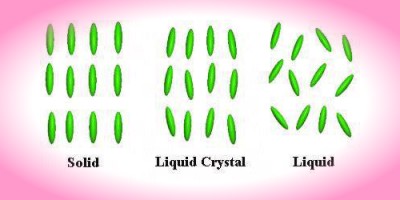
The distinguishing characteristic of the liquid crystalline state is the tendency of the molecules (mesogens) to point along a common axis, called the director. This is in contrast to molecules in the liquid phase, which have no intrinsic order. In the solid state, molecules are highly ordered and have little translational freedom. The characteristic orientational order of the liquid crystal state is between the traditional solid and liquid phases and this is the origin of the term mesogenic state, used synonymously with liquid crystal state. Note the average alignment of the molecules for each phase in the following diagram.
It is sometimes difficult to determine whether a material is in a crystal
or liquid crystal state. Crystalline
materials demonstrate long range periodic order in three dimensions. By
definition, an isotropic
liquid has no orientational order. Substances that aren't as ordered as a
solid, yet have some degree of alignment are properly called liquid
crystals.
Characterizing Liquid Crystals
The following parameters describe the liquid crystalline structure:
Most liquid crystal compounds exhibit polymorphism, or a condition where more than one phase is observed in the liquid crystalline state. The term mesophase is used to describe the "subphases" of liquid crystal materials. Mesophases are formed by changing the amount of order in the sample, either by imposing order in only one or two dimensions, or by allowing the molecules to have a degree of translational motion. The following section describes the mesophases of liquid crystals in greater detail.
External Influences on Liquid Crystals
Scientists and engineers are able to use liquid crystals in a variety of applications because external perturbation can cause significant changes in the macroscopic properties of the liquid crystal system. Both electric and magnetic fields can be used to induce these changes. The magnitude of the fields, as well as the speed at which the molecules align are important characteristics industry deals with. Finally, special surface treatments can be used in liquid crystal devices to force specific orientations of the director.
Liquid crystals are found to be birefringent, due to their anisotropic nature. That is, they demonstrate double refraction (having two indices of refraction). Light polarized parallel to the director has a different index of refraction (that is to say it travels at a different velocity) than light polarized perpendicular to the director.
Thus, when light enters a birefringent material, such as a nematic
liquid crystal sample, the process is modeled in terms of the light being
broken up into the fast (called the ordinary ray) and slow (called the
extraordinary ray) components. Because the two components travel at
different velocities, the waves get out of phase. When the rays are
recombined as they exit the birefringent material, the polarization state
has changed because of this phase difference. Light traveling through a birefringent medium
will
take one of two paths depending on its polarization.
The length of the sample is another important parameter because the phase shift accumulates as long as the light propagates in the birefringent material. Any polarization state can be produced with the right combination of the birefringence and length parameters.
Application to Polarized Light Studies of Liquid Crystals
Consider the case where a liquid crystal sample is placed between crossed polarizers whose transmission axes are aligned at some angle between the fast and slow direction of the material. Because of the birefringent nature of the sample, the incoming linearly polarized light becomes elliptically polarized. When this ray reaches the second polarizer, there is now a component that can pass through, and the region appears bright. For monochromatic light (single frequency), the magnitude of the phase difference is determined by the length and the birefringence of the material. If the sample is very thin, the ordinary and extraordinary components do not get very far out of phase. Likewise, if the sample is thick, the phase difference can be large. If the phase difference equals 360 degrees, the wave returns to its original polarization state and is blocked by the second polarizer. The size of the phase shift determines the intensity of the transmitted light.
If the transmission axis of the first polarizer is parallel to either the ordinary or extraordinary directions, the light is not broken up into components, and no change in the polarization state occurs. In this case, there is not a transmitted component and the region appears dark.
In a typical liquid crystal, the birefringence and length are not constant over the entire sample. This means that some areas appear light and others appear dark. The Schlieren texture, as this particular arrangement is known, is characteristic of the nematic phase. The dark regions that represent alignment parallel or perpendicular to the director are called brushes. The next section will describe the textures of liquid crystals in greater detail, but before going there lets see how birefringence can lead to multicolored images in the examination of liquid crystals under polarized white light.
Colors Arising From Polarized Light Studies
In understanding the origin of the colors which are observed in the studies of liquid crystals placed between crossed linear polarizers, it will be helpful to return to the examples of retarding plates discussed in the Birefringence Simulation. They are designed for a specific wavelength and thus will produce the desired results for a relatively narrow band of wavelengths around that particular value. If, for example, a full-wave plate designed for wavelength is l¢ is placed between crossed polarizers at some arbitrary orientation and the combination illuminated by white light, the wavelength l¢ will not be affected by the retarder and so will be extinguished (absorbed) by the analyzer. However, all other wavelengths will experience some retardation and emerge from the full-wave plate in a variety of polarization states. The components of this light passed by the analyzer will then form the complementary color to l¢.
Color patterns observed in the polarizing microscope, together with the extinctions already noted in the connection with the Birefringence Simulations are very useful in the study of liquid crystals in many situations, including the identification of textures, of liquid crystal phases and the observations of phase changes.
The liquid crystals allow you to adjust the birefringence, the length, and the orientation, q, of the liquid crystal sample. Here, q is the angle between the director and the vertical direction (The transmission direction of the polarizer).
Liquid Crystal Textures
The term texture refers to the orientation of liquid crystal molecules in the vicinity of a surface. Each liquid crystal mesophase can form its own characteristic textures, which are useful in identification.
If mesogenic materials are confined between closely spaced plates with rubbed surfaces (as described above) and oriented with rubbing directions parallel, the entire liquid crystal sample can be oriented in a planar texture. Mesogens can also be oriented normal to a surface with the use of appropriate polymer films, or in the presence of an electric field applied normal to the surface, giving rise to the homeotropic texture.
Chemical Properties of Liquid Crystals
Liquid crystals can be classified into two main categories: thermotropic liquid crystals, and lyotropic liquid crystals. These two types of liquid crystals are distinguished by the mechanisms that drive their self-organization, but they are also similar in many ways.
Thermotropic transactions occur in most liquid crystals, and they are defined by the fact that the transitions to the liquid crystalline state are induced thermally. That is, one can arrive at the liquid crystalline state by raising the temperature of a solid and/or lowering the temperature of a liquid. Thermotropic liquid crystals can be classified into two types: enantiotropic liquid crystals, which can be changed into the liquid crystal state from either lowering the temperature of a liquid or raising of the temperature of a solid, and monotropic liquid crystals, which can only be changed into the liquid crystal state from either an increase in the temperature of a solid or a decrease in the temperature of a liquid, but not both. In general, thermotropic mesophases occur because of anisotropic dispersion forces between the molecules and because of packing interactions.
Lyotropic liquid crystal transitions occur with the influence of solvents, not by a change in temperature. Lyotropic mesophases occur as a result of solvent-induced aggregation of the constituent mesogens into micellar structures. Lyotropic mesogens are typically amphiphilic, meaning that they are composed of both lyophilic (solvent-attracting) and lyophobic (solvent-repelling) parts. This causes them to form into micellar structures in the presence of a solvent, since the lyophobic ends will stay together as the lyophilic ends extend outward toward the solution. As the concentration of the solution is increased and the solution is cooled, the micelles increase in size and eventually coalesce. This separates the newly formed liquid crystalline state from the solvent.
A very large number of chemical compounds are known to exhibit one or several liquid crystalline phases. Despite significant differences in chemical composition, these molecules have some common features in chemical and physical properties. There are two types of thermotropic liquid crystals: discotics and rod-shaped molecules. Discotics are flat disc-like molecules consisting of a core of adjacent aromatic rings. This allows for two dimensional columnar ordering. Rod-shaped molecules have an elongated, anisotropic geometry which allows for preferential alignment along one spatial direction.
Applications of Liquid Crystals
Liquid crystal technology has had a major effect many areas of science and engineering, as well as device technology. Applications for this special kind of material are still being discovered and continue to provide effective solutions to many different issues.
Liquid Crystal Displays (LCDs)
The most common application of liquid crystal technology is liquid
crystal displays (LCDs.) This field has grown into a multi-billion dollar
industry, and many significant scientific and engineering discoveries have
been made.
Liquid Crystal Thermometers
Chiral nematic (cholesteric) liquid crystals
reflect light with a wavelength equal to the pitch. Because the pitch is
dependent upon temperature, the color reflected also is dependent upon
temperature. Liquid crystals make it possible to accurately gauge
temperature just by looking at the color of the thermometer. By mixing
different compounds, a device for practically any temperature range can be
built.
The "mood ring", a popular novelty a few years ago, took advantage of the unique ability of the chiral nematic liquid crystal. More important and practical applications have been developed in such diverse areas as medicine and electronics. Special liquid crystal devices can be attached to the skin to show a "map" of temperatures. This is useful because often physical problems, such as tumors, have a different temperature than the surrounding tissue. Liquid crystal temperature sensors can also be used to find bad connections on a circuit board by detecting the characteristic higher temperature.
Optical Imaging
An application of liquid crystals that is only now being explored is
optical imaging and recording. In this technology, a liquid crystal cell
is placed between two layers of photoconductor. Light is applied to the
photoconductor, which increases the material's conductivity. This causes
an electric field to develop in the liquid crystal corresponding to the
intensity of the light. The electric pattern can be transmitted by an
electrode, which enables the image to be recorded. This technology is
still being developed and is one of the most promising areas of liquid
crystal research.
Other Liquid Crystal Applications
Liquid crystals have a multitude of other uses. They are used for
nondestructive mechanical testing of materials under stress. This
technique is also used for the visualization of RF (radio frequency) waves
in waveguides. They are used in medical applications where, for example,
transient pressure transmitted by a walking foot on the ground is
measured. Low molar mass (LMM) liquid crystals have applications including
erasable optical disks, full color "electronic slides" for
computer-aided drawing (CAD), and light modulators for color electronic
imaging.
As new properties and types of liquid crystals are investigated and researched, these materials are sure to gain increasing importance in industrial and scientific applications.
Polymer Liquid Crystals (PLCs)
Polymer liquid crystals (PLCs) are a class of materials that combine the properties of polymers with those of liquid crystals. These "hybrids" show the same mesophases characteristic of ordinary liquid crystals, yet retain many of the useful and versatile properties of polymers.
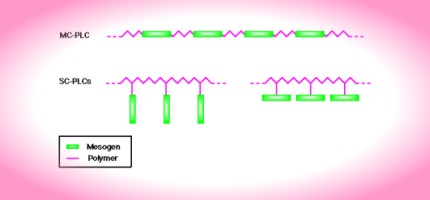
In order for normally flexible polymers to display liquid crystal characteristics, rod-like or disk-like elements (called mesogens) must be incorporated into their chains. The placement of the mesogens plays a large role in determining the type of PLC that is formed. Main-chain polymer liquid crystals or MC-PLCs are formed when the mesogens are themselves part of the main chain of a polymer. Conversely, side chain polymer liquid crystals or SC-PLCs are formed when the mesogens are connected as side chains to the polymer by a flexible "bridge" (called the spacer.)
Other factors influencing the mesomorphic behavior of polymers include the presence of long flexible spacers, a low molecular weight, and regular alternation of rigid and flexible units along the main chain.
Main Chain Polymer Liquid Crystals
Main chain polymer liquid crystals are formed when rigid elements are incorporated into the backbone of normally flexible polymers. These stiff regions along the chain allow the polymer to orient in a manner similar to ordinary liquid crystals, and thus display liquid crystal characteristics. There are two distinct groups of MC-PLCs, differentiated by the manner in which the stiff regions are formed.
The first group of main chain polymer liquid crystals is characterized by stiff, rod-like monomers. These monomers are typically made up of several aromatic rings which provide the necessary size.
The second and more prevalent group of main chain polymer liquid crystals is different because it incorporates a mesogen directly into the chain. The mesogen acts just like the stiff areas in the first group. Generally, the mesogenic units are made up of two or more aromatic rings which provide the necessary restriction on movement that allow the polymer to display liquid crystal properties. The stiffness necessary for liquid crystallinity results from restrictions on rotation caused by steric hindrance and resonance. Another characteristic of the mesogen is its axial ratio. The axial ratio is defined to be the length of the molecule divided by the diameter ( x = L/d ). Experimental results have concluded that these molecules must be at least three times long as they are wide. Otherwise, the molecules are not rod-like enough to display the characteristics of liquid crystals.
This group is different from the first in that the mesogens are separated or "decoupled" by a flexible bridge called a spacer. Decoupling of the mesogens provides for independent movement of the molecules which facilitates proper alignment.
Side Chain Polymer Liquid Crystals
It has been demonstrated that main chain polymer liquid crystals often cannot show mesogenic behavior over a wide temperature range (see Main Chain Polymer Liquid Crystals). Side chain polymer liquid crystals, however, are able to expand this scale. These materials are formed when mesogenic units are attached to the polymer as side chains.
Side chain polymer liquid crystals have three major structural components: the backbone, the spacer, and the mesogen. The versatility of SC-PLCs arises because these structures can be varied in a number of ways.
The backbone of a side chain polymer liquid crystal is the element that the side chains are attached to. The structure of the backbone can be very important in determining if the polymer shows liquid crystal behavior. Polymers with rigid backbones typically have high glass transition temperatures, and thus liquid crystal behavior is often difficult to observe. In order to lower this temperature, the polymer backbone can be made more flexible.
Perhaps the most important part of a side chain polymer liquid crystal is the mesogen. It is the alignment of these groups that causes the liquid crystal behavior. Usually, the mesogen is made up of a rigid core of two or more aromatic rings joined together by a functional group. The following diagram is a typical repeating unit in a side chain polymer liquid crystal. Notice the spacer of methylene units and the mesogen of aromatic rings.
Like their main chain counterparts, mesogens attached as side groups on the backbone of side chain polymer liquid crystals are able to orient because the spacer allows for independent movement. Notice that even though the polymer may be in a tangled conformation, orientation of the mesogens is still possible because of the decoupling action of the spacer.
The structure of the spacer is an important determining factor in side chain polymer liquid crystals. Generally, the spacer consists of two to four methylene (CH2) groups attached together in a line. Accordingly, the spacer length has a profound effect on the temperature and type of phase transitions. Usually, the glass transition temperature decreases with increasing spacer length. Short spacers tend to lead to nematic phases, while longer spacers lead to smectic phases.
Phases of Polymer Liquid Crystals
Polymer liquid crystals form the same mesophases as ordinary liquid crystals. Understanding the ways in which the molecules line up is important in understanding their properties.
Side chain polymer liquid crystals show a tendency to separate the backbone from the mesogenic side groups. This is achieved in the smectic phase where the mesogenic groups and backbone chains form individual layers.
Many side chain polymer liquid crystals form what is known as the "double comb" configuration. This structure is formed when side chains point away from the backbone in an alternating fashion. The double comb configuration allows the polymers to form layers characteristic of the smectic phase.
Atactic polymers in addition to copolymers cannot form this structure because the side chains are connected to the backbone in random directions.
Applications of Polymer Liquid Crystals
Polymer liquid crystals will most certainly become more important as research into this field progresses. Applications for these materials range from the production of high-strength materials to their use in optical devices.
High-Strength Fibers
An application of polymer liquid crystals that has been successfully
developed for industry is the area of high strength fibers. Kevlar, which
is used to make such things as helmets and bullet-proof vests, is just one
example of the use of polymer liquid crystals in applications calling for
strong, light weight materials.
Ordinary polymers have never been able to demonstrate the stiffness necessary to compete against traditional materials like steel. It has been observed that polymers with long straight chains are significantly stronger than their tangled counterparts. Main chain liquid crystal polymers are well-suited to ordering processes. For example, the polymer can be oriented in the desired liquid crystal phase and then quenched to create a highly ordered, strong solid. As these technologies continue to develop, an increasing variety of new materials with strong and light-weight properties will become available.
Optical Applications
The use of polymer liquid crystals in the display industry is an
exciting area of research. At this time, PLC's demonstrate relatively slow
"response times" to electric fields. That is, when a field is
applied, the molecules take a long time to align along it. This is not a
good property for use in displays where the screen must be able to change
rapidly from one view to another. Researchers are working to overcome this
problem because the manipulation of polymers is often much easier than
traditional liquid crystals.
In applications for which response time is not a factor (or in the future, after response times have improved), a twisted nematic polymer liquid crystal cell can be used to make energy efficient displays. A laser is used to selectively melt portions of the display into the liquid crystal phase. The orientation of the cell is then chosen by applying a field across it, just as in an ordinary twisted nematic liquid crystal cell. When the polymer cools down and hardens into a glass, the mesogens will be locked in that configuration and the field can be turned off.
Side chain polymer liquid crystals exhibit good properties for applications in optically nonlinear devices including optical waveguides and electro-optic modulators in poled polymeric slab waveguides. More devices are expected to be fabricated from PLCs in the future: optically-addressed spatial light modulators, tunable notch filters, optical amplifiers, and laser beam deflectors. The properties of ferroelectric chiral smectic C phases make this material useful for films with applications in nonlinear optics.
Polymer-Dispersed Liquid Crystals
(PDLCs)
Polymer-dispersed liquid crystals (PDLCs) are a relatively new class of
materials that hold promise for many applications ranging from switchable
windows to projection displays. These materials, which are simply a
combined application of polymers and liquid crystals, are the focus of
extensive research in the display industry.
PDLCs consist of liquid crystal droplets that are dispersed in a solid polymer matrix. The resulting material is a sort of "swiss cheese" polymer with liquid crystal droplets filling in the holes. These tiny droplets (a few microns across for practical applications) are responsible for the unique behavior of the material. By changing the orientation of the liquid crystal molecules with an electric field, it is possible to vary the intensity of transmitted light.
Polymer-dispersed liquid crystals have been prepared in several different ways including: encapsulation (emulsification) and phase separation; the latter process has become the primary method of manufacture. Each method produces PDLCs with different properties and characteristics. Among the factors influencing the properties of the PDLC material are the size and morphology (shape) of the droplets, the types of polymer and liquid crystal used, and cooling and heating rates in production.
Applications of PDLCs
Polymer-dispersed liquid crystals hold potential for a variety of electro-optic applications ranging from displays to light shutters. Below, we illustrate their applications as electro-optic light shutters in the construction of privacy windows.
PDLC windows are based on the ability of the nematic director of the liquid crystal droplets to align under an electric field as discussed in the previous section (also see Electric and Magnetic Field Effects). In a typical application, a thin PDLC film (about 25 microns thick) is deposited between clear plastic covers. The plastic substrates are coated with a very thin layer of a conducting material known as indium tin oxide (ITO).
Transmission of light through a PDLC window depends primarily on scattering which in turn depends on the difference in refractive index between droplets and their environment. In the case of high droplet density, the environment consists mainly of other droplets, which makes the relative orientation of their directors an important factor. The droplets are anisotropic with the index of refraction parallel to the director different from that perpendicular to it.
In the field OFF, the random array of droplet orientation provides significant differences in indices and hence strong scattering. In this state, the cell appears opaque. When a voltage is applied, however, the director of the individual droplets align with the field. There is now little difference in refractive index for neighboring droplets, and the cell appears transparent.
Polymer Stabilized Liquid Crystals (PSLCs)
Applications of dispersions containing polymers and liquid crystals are
growing in importance. The preceding section on Polymer
Dispersed Liquid Crystals (PDLC) dealt with a higher polymer
concentration range, above about 20-wt %. In display applications, these
materials present problems with hazy images for obliquely incident light.
Rapid development is occurring in the low polymer concentration range (10
weight % or less) because of the ability to form polymer networks which
stabilize liquid crystal textures throughout the bulk of a device and
improve its electro-optical performance, as discussed later. Just as in
the case of PDLCs, ALCOM researchers have played leading roles in the
discovery, investigation and development of these polymer stabilized
liquid crystalline (PSLC) materials for use in devices.
Polymer Stabilized Nematic Liquid
Crystals
Studies of the influence of polymer networks on devices which employ nematic materials include twisted nematic (TN) and supertwisted nematic (STN) liquid crystal devices (LCD). One such investigation by Bos, et al, was reported in 1996. They found that, in TN cells, a significant reduction in operational voltage can be achieved at low polymer concentration and, in STN cells, the undesirable striping texture can be eliminated and a reduction in driving voltage achieved.
In these and other applications of devices based on polymer stabilization, it is important to understand the role of the polymer network and its morphology as well as the factors controlling it. Another group of ALCOM researchers, Hudson, Rajaram, and Chien (Rajaram, 1996) made use of nematic liquid crystal materials in an important study of the effect of monomer structure and temperature of photopolymerization on network morphology. They also developed a kinetic model of the network formation as described and illustrated below.
Morphology of Polymer Network
PSLC cells are generally prepared by dissolving and photopolymerizing
monomers (typically less than 5 wt%) in a liquid crystals matrix to form a
polymer network. Hudson, et al. (Rajaram, 1996), chose to study
network formation in a nematic liquid crystal matrix (solvent) of planar
(homogeneous) aligned nematic liquid crystal as well as in an isotropic
environment. The homogeneous alignment was provided by
pretreatment--coating and rubbing--of the inner side of the bounding glass
cell faces. The particular sample solutions of interest in this brief
summary contain 3 wt% of either the diacrylate monomer BAB or BAB6 with
0.3 wt% photoinitiator BME dissolved in E48, a eutectic mix of several
similar low-molar mass liquid crystals.
After being sandwiched between the treated glass cell faces, the solution was photopolymerized under an UV light source. Here, polymer phase separation and network formation take place. In some studies the liquid crystal matrix was then dissolved by placing the cell in hexane (2 days). Finally, the cell was carefully split open to permit study of the bare polymer network using the scanning electron microscope (SEM). It has recently been discovered that normal evaporation of hexane or ethanol leads to tearing of the network, while a more faithful representation of both small scale (nodular clusters) and large scale (network) structure is preserved by super critical drying in CO2.
Polymer Stabilized Cholesteric Liquid Crystals
Cholesteric Liquid Crystals have many applications as electro-optic materials in thin film devices in much the same way as nematic liquid crystals do. The presence of a polymer network formed at low polymer concentrations provides similar advantages in enhancing the stability of the structure, aiding in the return of the liquid crystal director orientation to the desired stable configuration, reducing the switching time, and helping to determine and maintain the poly-domain size.
In the planar texture, cholesteric liquid crystals display selective reflection. The reflected intensity plot over the visible spectrum shown below illustrates this, with maximum reflection occurring at a wavelength equal to the pitch, which may be pre-selected by choices of materials. This represents the reflection of one handedness of circularly polarized light due to periodic variations of the index of refraction of the material. The other handedness is transmitted through the cholesteric material.
Polymer networks are formed in cholesterics during the initial stages of film preparation by combining a small quantity of reactive monomer and photoinitiator with the cholesteric liquid crystal molecules, just as in the case of the nematics. In fact, the process can be identical, except that a small amount of chiral dopant is added to produce the desired cholesteric pitch. After the desired texture is established through the combination of surface preparations and applied field, ultraviolet light is used to photopolymerize the sample. The morphology of the resulting polymer network mimics the textures of ordinary cholesteric mesophases. Such a network is schematically illustrated by the blue lines in the figure below (shown in the focal conic texture). These polymer stabilized cholesteric textures are sometimes referred to by the acronym PSCT.
Studies of the network formed in cholesterics have been reported by several groups including the ALCOM researchers mentioned in the discussion of stabilization of nematics (Rajaram, 1996 and Dierking, 1997). Just as in the case of nematics, after removal of the liquid crystal material, SEM and special optical microscopy have shown a fiber-like anisotropic network whose morphology has been influenced by the presence of the liquid crystal, including evidence of the helical cholesteric texture. In turn, the network influences the structure of the focal conic state and stabilizes initial states. Factors controlling morphology, such as liquid crystal texture, monomer concentration, photopolymerization temperature, UV intensity and exposure time have been explored and discussed in those references.
Applications of Polymer Stabilized Cholesterics Liquid CrystalsThe helical structure of cholesterics leads to unusual optical properties as noted earlier and the inclusion of polymer networks can provide important advantages. We discuss here two different device applications which made use of some of these properties: The reflective cholesteric liquid crystal display and the light shutter.
Bistable Reflective Cholesteric Liquid Crystal Displays
When the pitch
of the cholesteric material lies in the range of visible wavelengths, the
property of selective reflection from the planar cholesteric texture in
contrast to the partial or full transmission through the focal conic and
homeotropic textures provides opportunities for a variety of display
applications. For example, in the planar state, a polymer stabilized
cholesteric cell reflects incident light, and appears bright. In the
focal-conic state, the incident light is transmitted through the cell and
reveals the color of the coating on the rear of the window.
Fortunately, both of these states are stable at E=0. This means that the textures are "locked in" and will remain intact until acted upon again (i.e. the device is bistable). Switching from planar to focal conic requires a low voltage pulse while the return from focal conic to planar requires a higher voltage pulse to drive the device into a homeotropic state which then relaxes through a transient planar texture to the final planar state (Chap 5 &12, Crawford and Zumer, 1996; Huang, 1997).
Bistable reflective cholesteric cells are prepared (as described earlier, in connection with the formation of networks in Polymer Stabilized Cholesterics) to have an appropriately short pitch and then photopolymerized in the initial planar state. As discussed there, the polymer network breaks up the planar texture into small domains which are only slightly misoriented from each other. These polydomains respond more rapidly to the switching waveform than would bulk material, an important factor for many display purposes. In addition, a good gray scale operation can be achieved through choice of polydomain sizes and switching waveforms. Even more exciting is the fact that color displays are now possible through the use of either layered cholesteric cells, or the formation of pixels. For the layered cholesterics, each layer is set to a different optical pitch to reflect different colors. The pixel cells work much like in other system by having each pixel contain one specific color ready to be turned on or off.
Among the other advantages in devices employing bistable reflective cholesteric material is their relatively low power requirement, due to the ability to hold pixels in either reflective or transmitting states at no field, in addition to their use of reflected light (in comparison with the traditional LCD which requires backlighting and polarizers). They also offer the possibility of highly multiplexed passive displays and of the use of plastic substrates which have non-uniform birefringence but, in this case, do not enter the optical path. The ease of polymer network bonding to plastic substrates offers mechanical stability, as well. Finally, while video rates are not yet available, and reflective brightness still needs improvements, research in materials and in drive methods continues to show promising developments. In the meantime, some improvements in current technology should yield several possible applications including electronic books and newspapers.
Light Shutters
By lengthening the cholesteric liquid crystal pitch to the order of
infra-red wavelengths, the bistable effect at zero applied electric field
is avoided. Instead, the choice of either planar or focal conic stable
state is determined by initial conditions at the time of polymer network
formation, as discussed below. The starting materials are the same as
those used in the bistable reflecting cholesteric except for a reduction
in concentration of the chiral agent to lengthen the cholesteric pitch. We
treat the reverse mode shutter first since more polymer network studies
have been carried out in this configuration, then move on to the normal
mode shutter and illustrate its characterization with a simulation.
Reverse mode light shutter
In preparation of a reverse mode cell, a solution of longer pitch
cholesteric material containing a few percent of reactive monomers is
placed between two glass plates whose inner surfaces have been coated with
a transparent conducting material, such as indium-tin oxide (ITO), to form
electrodes and then prepared to yield a planar texture.
Photopolymerization in the absence of an applied field yields a polymer
network which stabilizes this planar texture. The network is predominantly
oriented parallel to the glass plates. As illustrated in the figure below,
visible light is transmitted by the cell in the planar texture because the
pitch of the helices lies in the infra-red wavelength range. However,
under the application of a moderate electric field perpendicular to the
windows, the cholesteric material switches to a focal conic texture. This
strongly scatters visible light because of the index of refraction changes
at the polydomain boundaries between focal conic regions.
When the electric field is turned off, the cholesteric material relaxes back to the original planar texture. Such a cell can be reliably cycled between these two states many times.
Application of a very high electric field will switch the cholesteric material to an untwisted homeotropic texture. This can deform the polymer network sufficiently that the material no longer returns to the original transparent planar texture when the field is turned off. Hence, caution must be exercised in such tests. The following movie schematically demonstrates the electric field response of cholesteric material in the presence of a polymer network formed in the reverse mode configuration. In the case of this movie, for simplicity, the red triangles represent a full or at least a partial helix but illustrate an average director orientation of a few liquid crystal layers only near the center of the helix. There is no significance to the fact that they all point in the same direction in the planar state shown with the field off.
Dierking, et al (Dierking, 1997) have studied factors affecting the polymer network and its morphology as well as their influence on the electro-optic properties of reverse mode polymer stabilized cholesteric cells. Among other things, they have discovered a two stage reorientation effect in a study of the switching process between the planar and focal conic textures. For sufficiently low polymer concentration, the cholesteric material in the vicinity of the polymer network experiences elastic interactions which accelerate its relaxation and reorientation while the cholesteric material in the network voids behaves in more of a bulk-like manner, exhibiting a more extended relaxation.
Normal mode light shutters
Normal mode cells are photopolymerized in the homeotropic texture
produced by a strong electric field. When the electric field is removed
the cell settles into the focal conic texture. In the absence of an
electric field the cell scatters light and is opaque. With the application
of an electric field the cell is once again transparent.
With regard to electro-optic properties, transmittance for both the normal and reverse mode cells depends on the voltage applied to the cell. As the voltage across a normal mode cell increases, the transmittance increases. A low voltage yields a low transmittance, whereas a high voltage produces the transparent homeotropic texture, with high transmittance because the index of refraction is quite uniform throughout the liquid crystal material. This is in contrast with the focal conic case (off-state) where the index variation across focal-conic boundaries yields strong light scattering. The normal mode cell exhibits significant hysteresis in the dependence of its transmittance with voltage, as illustrated in the following simulation, while the reverse mode cell does not.
The transmittance of a reverse mode cell increases as the voltage decreases; maximum transmittance occurs at zero voltage. With a steady increase in voltage, there is initially no change until a transition stage is reached where the liquid crystal material begins to enter the focal conic texture and the transmittance decreases. The reverse mode cell’s minimum transmittance occurs at high voltage.
In light shutter applications, the choice of mode depends upon the desired operations, but there is relatively little variation in transmission across the visible wavelength spectrum exhibited in either mode and they both have a wide viewing angle. Yang, et al (chap 5, Crawford & Zumer, eds, 1996) discuss characteristics in much greater detail as well as the factors which influence application.
To view representative electro-optical properties of normal mode cells and how these measurements are made, please see the simulation linked above.
Polymer Walls in PSCTs
As discussed in the Polymer
Stabilized Cholesteric Liquid Crystals section, photocurable monomers
dispersed in a cholesteric liquid crystal mixture form a bistable, polymer
stabilized cholesteric texture (PSCT). Initially, low concentrations of
the monomer were used. This was done because high concentrations yielded
dense polymer networks in the liquid crystal. This would result in
significant light scattering in the focal conic state, which should only
weakly scatter the light. Thus, there is less contrast between this state
and the planar state, which reflects the light. Color purity and
brightness is also reduced by the light scattering. However, high
concentrations are of interest for their structural benefit. For example,
they provide a self-adhering and self-sustaining structure necessary for
flexible devices of large area on polymer substrate.
Polymer walls make use of high polymer content without adversely affecting the electro-optic characteristics as reported by ALCOM researchers (Kim, 1998). In a pixel array, these walls are formed in the interpixel region such that the polymer network is not very dense in the liquid crystal region. There are two ways to produce the polymer wall. One involves irradiating only selective areas of a cell containing ultra-violet (UV) curable monomers and liquid crystal with UV light through a photomask. This causes the phase separation by photopolymerization such that the polymer only exists in those regions where the UV light was allowed to pass through. The reason this occurs is that the monomer polymerizes in this region, thereby reducing the concentration of monomer. Due to the concentration gradient, more monomers disperse into this region and polymerize as well until most of the monomers have been polymerized in what becomes the interpixel region.
The second method uses the same materials but the polymer is attracted to the interpixel region by a patterned electric field. This is done by etching a cross pattern of indium tin oxide (ITO) on the substrate. The temperature is then decreased to phase separate the sample while an electric field is applied by means of the ITO. This field causes the monomer to segregate into the low field region, i.e. areas where the ITO was not applied. The reason this occurs is that the liquid crystal mixture has a larger dielectric constant than the monomer and experiences a greater force from the fringing fields in the interpixel. This forces the liquid crystal molecules to the high-field regions, leaving the monomer in the low-field region. The monomer is then cured by blanket UV exposure. This forms the polymer walls that define the interpixel region and leaves the pixels rich in liquid crystal material, i.e. low monomer concentration. Further research into polymer walls has allowed the use of UV-cured monomers in both Twisted nematic (TN) and electrically controlled birefringence (ECB) displays. Although the choice of monomers in these curing processes is more restricted, the results are displays with an increased mechanical strength.
Phototuning
The planar state of PSCTs reflects light of a certain wavelength. For
light at normal incidence, the wavelength is given by Bragg's reflection
law, l = p * n, where p is the pitch and n is
the average refractive index. Thereby, a change in the pitch length of the
material would lead to a different wavelength of light being reflected.
Alcom researchers (Chien, 1998) have shown that a tunable chiral
material (TCM) can be used for such a purpose. When added to the
cholesteric formulation, it increases the chirality and thereby decreases
the pitch (initially the cholesteric formulation reflects red light and
after the TCM is added it reflects blue). Ultraviolet radiation
polymerizes the tunable chiral dopant such that its concentration
decreases. As the concentration decreases, the chirality of the mixture
decreases and the mixture's pitch increases. Thus, longer UV exposure
means the pitch of the mixture increases a greater amount and the
reflected wavelength increases proportionately according to Bragg's
reflection law (the reflected wavelength can be increased back to the
original wavelength, that of red light). However, bleeding or diffusion of
color may occur over time because of the concentration gradient due to the
varying concentration of the TCM. Linking the TCM to a polymer network can
be used to hold the TCM in place and prevent color diffusion. The downside
to this is the same as discussed above; more polymer content means poorer
reflectance and color brightness. Using TCMs with higher helical twisting
power would allow less to be used. Despite some problems still to be
overcome, TCMs allow a sequential array of the three primary colors to be
made from the same cholesteric mixture by exposing pixels to varying
amounts of UV light. As illustrated below, selective masking and repeated
UV exposure accomplishes the dual purpose of color patterning of pixels
through modifying the chirality of the TCM and photopolymerizing the
remaining monomer to produce the desired polymer network for device
stabilization.
Colored bistable reflectives possess the same primary advantage as the monochrome devices - very low power requirement. However, the rather complicated fabrication process needed for this TCM type in combination with uncertainty over the long term stability of the colors underscores the need for further development work in this area.
Lyotropic Liquid Crystals
Lyotropic liquid crystals were actually discovered long before their thermotropic counterparts were known. In 1850, their texture was noticed in a mixture of myelin and water. At the time of discovery, however, the significance of liquid crystals was not understood, so most research has been done on thermotropics. Only fairly recently have lyotropic liquid crystals begun to catch up.
The molecules that make up lyotropic liquid crystals are surfactants consisting of two distinct parts: a polar, often ionic, head and a nonpolar, often hydrocarbon tail. (Not all surfactants, however, form lyotropic liquid crystals.) Following the rule of "like dissolves like," the head is attracted to water, or hydrophilic, and the tail is repelled by water, or hydrophobic. When dissolved in high enough concentrations, the molecules arrange themselves so that the polar heads are in contact with a polar solvent and/or the nonpolar tails are in contact with a nonpolar solvent.
Lyotropic liquid crystals are found in countless everyday situations. Soaps and detergents form lyotropic liquid crystals when they combine with water. In the kitchen, cake batters may harbor the liquid crystals as well. Most importantly, biological membranes display lyotropic liquid crystalline behavior.
Structure and Properties of Lyotropic Liquid CrystalsLyotropic liquid crystal molecules belong to a class of substances called amphiphilic compounds. These compounds are characterized by a sort of split personality - one end of the molecule is polar and attracted to water while the other end is nonpolar and attracted to hydrocarbons, or lipophilic. The diagram to the left shows sodium laurate, a common amphiphilic molecule. In solution, the molecules situate themselves such that either the polar ends are dissolved in a polar solvent or the nonpolar ends are dissolved in a nonpolar solvent. The opposite end is kept isolated from the unlike solvent. As the concentration of the molecules in solution increases, they take on different arrangements or phases.
PhasesFor the purpose of this discussion, it will be assumed that the amphiphilic molecules are dissolved in water, so the molecules will be arranging themselves with the polar heads in contact with the water.
At low concentrations, the solution looks like any other - particles of solute distributed randomly throughout the water. When the concentration gets high enough, however, the molecules begin to arrange themselves in hollow spheres, rods, and disks called micelles. In some reactions, the type of micelle affects the reaction rate, most likely because the parts of the molecule involved in the reaction are more likely to be exposed in some formations than in others. The surface of a micelle is a layer of polar heads dissolved in the water, while the inner portion consists of hydrophobic tails screened from the water by the hydrophilic heads. Micelles come in varied sizes, but the smallest ones have a diameter about twice as long as the length of a hydrocarbon chain with all trans- bonds. As the weight concentration of amphiphile increases, the micelles become increasingly able to dissolve nonpolar substances. When this occurs, the micelles become large and swollen. If they reach a large enough size, the solution becomes cloudy and is called an emulsion. At lower concentrations, the swollen micelles are not large enough to interfere with light, but they are still extremely stable and exist in equilibrium. This phase is referred to as a microemulsion.
 |
 |
| Spherical micelle | Cross-section |
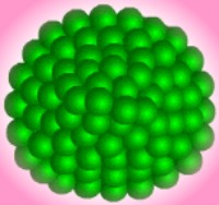
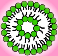
As the concentration increases, the micelles begin to arrange themselves into loose patterns. These patterns are the actual liquid crystal aspects of the molecular behavior. One of the first liquid crystal phases has micelles forming a structure similar to a face-centered or body-centered cubic crystal lattice. The illustration below shows a body-centered cubic crystal structure. Micelles take the place of individual atoms, ions, or molecules. It should also be noted that the pattern is not as stable or as rigid as that of a solid crystal like graphite or table salt, hence the term liquid crystal. Rod-shaped micelles often form into hexagonal arrays made out of six rods grouped around a central one for a total of seven, as illustrated in the picture below. In the enlargement of a single rod, notice that the micelle surface is composed of hydrophilic heads. The hydrophobic tails are isolated inside the micelle. Hexagonal liquid crystals generally exist in solutions that are forty to seventy percent amphiphile. The liquid crystals may come apart if too much water or salt is added to the solution, but many varieties can absorb oil by expanding the diameter of the rod-shaped micelle.
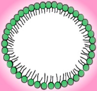
At even higher concentrations the molecules move into another liquid crystalline phase - the lyotropic liquid crystal bilayer. This structure has a double layer of molecules arranged a bit like a sandwich with polar heads taking the place of the bread and nonpolar tails as the filling. This pattern is similar to that of smectic liquid crystals in the thermotropic category. Because the sheet-like layers can slide easily past each other, this phase is less viscous than the hexagonal phase, at least in the direction of the sliding, despite its lower water content. The bilayer, or lamellar, phase has a focal conic texture. (See the section on liquid crystal phases for more information.) Another structure, called the ribbon phase, may be the precursor to the bilayer. Ribbon phases involve finite bilayers that end in cylindrical half-micelles. Bilayers may form when these ribbons fuse together. Lyotropic liquid crystals rarely exist in solutions that are less than half amphiphile by weight. If the amphiphile concentration is lower, the mixture reverts to a hexagonal phase or a solution of micelles.
Amphiphilic monolayer
Other behaviors occur when the situation is something
other than a simple water solution. If the molecules are placed on the
surface of water without actually being dissolved in it, they form a monolayer
in which the polar heads are in contact with the water and the hydrophobic
tails point into the air. These monolayers are often referred to as
Langmuir films and are a subject under investigation by ALCOM.
The following generic sort of phase diagram shows the changes in structure as concentration of amphiphilic molecules increases. The concentration at which micelles form in solution, called the critical micelle concentration, is shown as a dotted line. Also notice the dark line below which few liquid crystals form. This line represents a boundary temperature, referred to as the Krafft temperature. Below the Krafft temperature, a few liquid crystals may be suspended in the solution, but for the most part the amphiphilic molecules stay widely distributed. The reasons for this phenomenon will be explored in the next section. For further information, the Physics Today article (Pershan, 1982) covering the topic is recommended.
If the concentration by weight of amphiphilic molecules is higher than that of water, the molecules form a sort of matrix with water droplets scattered inside, in contact with the polar heads. If the molecules are dissolved in a nonpolar solvent, their behavior is similar to that when dissolved in water, except that now the nonpolar tails are in contact with the solvent and the polar heads are isolated in the centers of the micelles and bilayers. If the solution contains both water and a higher concentration of nonpolar solvent, similar inverse micelles form with water droplets quarantined inside the micelle and nonpolar solvent on the outside. See the illustration to the left for a cross-section of one of these reverse micelles. Finally, if weaker amphiphilic molecules and simple salts are dissolved together in water, they form "lyotropic nematic phases." In these crystals, as in thermotropic nematics, the director orientation can be changed by applying a magnetic field.
If water, a hydrocarbon, and a surfactant are mixed together, it is possible to get a microemulsion known as a ringing gel. This phase forms when micelles shift from rod to sphere shapes in the presence of a hydrocarbon. If the gel is placed in a container and the container is tapped, the gel will vibrate with an audible resonance frequency.
Other interesting behaviors can arise if a polymer is in solution with the amphiphilic molecules. Sometimes polymers will adsorb to micelles, creating a group of micelles all in a row like a necklace. Anionic amphiphiles form micelles at lower concentrations when a polymer is present in the solution. Other liquid crystals will break down into small micelles in the presence of a polymer. If a polymer is caught between the two sides of a bilayer it can poke holes right through. It is also possible for micelles adsorbed to a polymer to coexist in solution with free micelles.
Intermolecular Chemistry and Lyotropic
Structures
The dual nature of amphiphilic substances leads to a
struggle between the hydrophilic heads attempting to increase their
contact with water and the hydrophobic tails trying to avoid it. This
tension leads to a sort of compromise - an optimal surface area for the
water-amphiphile interface specific to each type of molecule. The shapes
in which the molecules arrange themselves depend partly on the optimal
surface area, as well as partly on the fluid volume of the hydrocarbon
chains and the maximum length at which they can still be considered fluid.
Although many structures can fit the geometry, one is usually best from a
thermodynamic perspective. Large structures create too much order, while
small structures cause the surface area to be larger than optimal, so a
medium-sized structure usually wins out.
 Vesicles are bilayers that have folded into a
three-dimensional spherical structure, sort of like a micelle with two
layers of molecules. Vesicles form because they get rid of the edges of
bilayers, protecting the hydrophobic chains from the water, but they still
allow for relatively small layers. In order for a flat bilayer to be
without edges, it would have to be infinite. Molecules that form vesicles
usually have a fluid double chain and a large optimal area. Lipids found
in biological membranes spontaneously form vesicles in solution. Please
refer to the illustration to the left for a cross-section of a vesicle.
Vesicles are bilayers that have folded into a
three-dimensional spherical structure, sort of like a micelle with two
layers of molecules. Vesicles form because they get rid of the edges of
bilayers, protecting the hydrophobic chains from the water, but they still
allow for relatively small layers. In order for a flat bilayer to be
without edges, it would have to be infinite. Molecules that form vesicles
usually have a fluid double chain and a large optimal area. Lipids found
in biological membranes spontaneously form vesicles in solution. Please
refer to the illustration to the left for a cross-section of a vesicle.
Under certain circumstances, as mentioned earlier, the amphiphiles can form inverse micelles, with the heads on the inside and tails on the outside. Molecules that form this structure usually have a small optimal interface area or a large chain volume to length ratio. Double chains, nonionic heads, and cis unsaturated chains are also common. When inverse micelles form, the solution changes from appearing as oil droplets in water to water droplets in oil.
Changes in Structure
The section above discussed some of the most common conditions for various geometries to form. Changing a few factors, however, can sometimes cause a structure to form where it wouldn't otherwise. This can be done by changing the head, changing the chain, or mixing different amphiphiles.
If a salt is added to the solution or if the pH is lowered, the hydrophilic interaction of the head is reduced and the optimal interface area is lowered. The additional ions in solution also reduce the repulsive interactions between head groups, reducing the radius of curvature. This makes the molecules more likely to form bilayers or inverse micelles. Using these methods to reduce the interface area often has the additional effect of straightening the hydrocarbon chains.
If the hydrocarbon chains are unsaturated or branched, their length is reduced. This increases the volume to length ratio and again makes bilayers and inverse micelles more likely.
When two different kinds of amphiphiles are mixed, the
characteristics of the solution are similar to an average of the
characteristics of solutions of the individual types, provided the two
types can mix freely in solution. Furthermore, carefully adding more of
one kind of molecule can cause the solution to form structures of
different shapes or sizes than either molecule would form alone.
These concepts relate to lyotropic liquid crystals by the fact that, for the amphiphilic molecules, the dominant form of entropy changes with concentration. At low concentrations, entropy is increased most by allowing the amphiphilic molecules to mix thoroughly with the water. As the concentration becomes higher, though, the order created by allowing organized structures becomes less important than the order created by forcing water molecules to rearrange themselves around dissolve hydrocarbons. At that point, structures begin to form in which the hydrocarbon tails are kept away from the water, preventing local order from increasing.
The strong role of entropy makes lyotropic liquid crystals different from most other substances. In many substances, order exists at low temperatures when the low enthalpy is enough to reduce the free energy. Disorder arises at higher temperatures when high entropy is needed to reduce the free energy. In lyotropic liquid crystals, though, structure exists at high concentrations when the order created by dissolving hydrocarbons would be larger than the disorder of having them randomly distributed through the water. At low concentrations, entropy plays its usual role of encouraging complete solvation and structures do not form.
Applications and Importance of Lyotropic Liquid Crystals
One material that demonstrates lyotropic liquid crystalline behavior is simple household soap. Soaps work better than pure water at removing dirt and grease because the nonpolar insides of the micelles are capable of dissolving nonpolar substances that will not dissolve in water. (This also works in reverse if the solvent is nonpolar and some of the substance to be removed is polar.) Soaps also help water dissolve more because the molecules tend to remain at the surface, hydrocarbon tail away from the water, thus lowering the surface tension of the water and allowing more material to enter it and be dissolved.
Other diverse applications exist for amphiphilic molecules. Because of their ability to dissolve both polar and nonpolar substances, a mixture of water and an amphiphilic compound can be pumped into a depleted oil well in order to remove much of the residual oil. In the medical professions, a lyotropic liquid crystal can coat a drug to keep it from being destroyed in the digestive tract. The drug can then be taken orally, and after it reaches the proper location in the body, the liquid crystal breaks down and the drug is released.
Lyotropic liquid crystals have been used to make a stable hydrocarbon foam. Hydrocarbon foams have been difficult to produce in the past because the surface tension of an the hydrocarbon is low enough that adsorption to an oil-soluble surfactant would have no significant effect. Without the adsorption, the hydrocarbon simply behaves as a liquid. When lyotropic liquid crystal molecules change from inverse micelles to lamellar sheets, they lower the surface tension enough for a foam to form. The hydrocarbon and the surfactant can dissolve in each other, and the surfactant cannot dissolve in water, although water can dissolve in the surfactant and mix into the liquid crystal.
Many other substances are also more soluble in lyotropic liquid crystals. One example is the drug hydrocortizone. It is often taken in topical applications, but its uses have been limited because the highest concentration possible has been only 1%. When the drug was blended into a liquid crystal of lecithin and water, the concentration went up to 4%. In time, liquid crystals may become a primary solvent for topical medications.
The outermost layer of skin is primarily a lyotropic liquid crystal made of fatty acids. At least some of the fatty acids must be unsaturated because saturated chains will simply crystallize rather than forming a liquid crystal structure. Experiments with crystals made only from saturated fatty acids produced layers that did not prevent water transport across them. This is a symptom that sometimes occurs in people whose diets are deficient in essential fatty acids of the sort found in unsaturated fats.
Biological Membranes
Lyotropic liquid crystals are also extremely important
because of their role in biological membranes. Membranes are composed of
amphiphilic lipids - mostly phospholipids and cholesterol, with a small
percentage of glycolipids. The phospholipids vary in the polar head
compositions and the hydrocarbon chain lengths, but almost all have two
hydrocarbon tails - one saturated and one unsaturated. These tails are
flexible, with the most freedom of movement found at the greatest distance
away from the polar head. (See the picture to the left for a
representative phospholipid structure and the one to the right for a
cholesterol structure.) Although there is still much to be learned about biological membranes, it
is now generally accepted that the lipids form lyotropic bilayers. In the
first experiment to provide evidence for a bilayer, all the lipids were
removed from red blood cell membranes, spread out on the surface of water,
and forced into a monolayer. The surface area was found to be twice the
surface area of the original red blood cells, suggesting that the
molecules were ordinarily in a double row. Further investigations have
supported the concept of an amphiphilic bilayer as the basic structure of
a cell membrane. Also evidence in its favor is the fact that the component
lipids form bilayers when dissolved in water even if they are not part of
a living cell. If the structure is caused by purely physical hydrophobic
interactions, then we do not need to ask how the cell creates or maintains
it. Those same hydrophobic interactions also cause any holes appearing in
the bilayer to immediately close, a very important characteristic for a
cell membrane.
The membrane also contains proteins, the placement of
which may be determined by the hydrophobic interaction. This would leave
polar parts of proteins on the outside exposed to water either inside or
outside the cell, while nonpolar parts would stay within the lipid bilayer,
isolated from the water on either side. It also seems likely that the
bilayer serves as a solvent for the various proteins and that it provides
contact with specific polar heads that may be needed for a protein to
function properly. The image of a cell membrane (lower right) shows lipids
in green and proteins interspersed through the membrane in blue.
Other interesting behaviors are found when bilayers with saturated and unsaturated lipids are studied. The bilayer then has two phase transition points, one for each kind of lipid. In these synthetic bilayers, lipids at their freezing point group together, separating the bilayer into regions composed of different lipids. Biological membranes, however, incorporate lipids with both a saturated and an unsaturated tail on each molecule, which makes the separations far less frequent. In the true biological membranes that have been studied, the lipids on the inside and outside layers have been different. In red blood cells, the molecules on the inner layer are less saturated, making the inner layer more fluid. Furthermore, one of the molecules found on the inside carries a net negative charge, causing a charge difference between the inside and the outside of the cell. The structure and function of biological membranes is currently an area of active research.
Ferroelectric Liquid Crystals (FLC)
The smectic C phase of liquid crystals first appeared in literature in 1933. However, it was not until 1974 that it was realized that the phase ought to be ferroelectric, meaning that the phase has a permanent polarization without the need for an electric field. This lead to further study of ferroelectric liquid crystals (FLC). In 1980 Clark and Lagerwall published the concept of the Surface Stabilized Ferroelectric Liquid Crystal (SSFLC) device. This was a major step forward in the possibility of useful applications of FLCs. It also led to large-scale development of FLC chemistry. As FLC products became more feasible, the technology became commercialized. The initial products appearing in 1989 were direct-view displays and print bars.
There is still major interest in FLC technology. This is due to the promise of fast switching and high resolution. These advantages and the possibility for dynamic gray scale and full color of SSFLC give it great potential for use in demanding applications such as high definition television (HDTV). The advantages do not come without some complications in production however. These difficulties explain the lack of major commercial breakthroughs in recent years.
FLCs have already been developed for miniature displays. These displays can be magnified or projected for a full screen image. They can also be used in head mounted displays such as those used for virtual reality. Such displays are highly portable and also allow for interactivity with the user (image changes as user's head turns). Since the display is supported by the user, weight is of great importance. The simplest way to reduce the weight of the system is to reduce the size of the screen needed (relatively lighter magnification devices can be used to increase the field of view). Meanwhile, the resolution must be high to make the image realistic to the user. FLC displays allow for this by their small pixel sizes. Also, FLCs can use reflective illumination to eliminate bulky (and high energy consuming) backlighting devices. The bistability offered by SSFLC devices makes them ideal where low energy consumption is a concern for still images since additional power is not required once image is created. Yet, their switching time is fast enough to provide high frame rates required for video. The fast switching time also allows full color on each pixel which means higher quality on a display of a given size.
Ferroelectric Liquid Crystal Structure
Rod-shaped molecules, mesogens, in the smectic phase show a translational order as well as orientational order as discussed in the Liquid Crystal Phases section. In the smectic C phase, the periodic spacing of the mesogens along one axis, we will use the z axis, causes them to form layers in the x-y plane. The director of each planar layer is tilted at an angle q from the normal. This angle is temperature dependent if a smectic C to smectic A transition occurs with increasing temperature.
Antiferroelectric Liquid Crystal
n the late 1980s, a different arrangement of the molecules in their layer plane was discovered. The phase is known as the antiferroelectric liquid crystal (AFLC) phase. This phase occurs in some materials at a temperature below the FLC phase. These materials, like FLCs, are chiral and possess a spontaneous polarization. The difference is that in the AFLC phase, the director is tilted in opposite direction in alternate layers.
As for the FLC, the AFLC helix must be unwound through a boundary constraint for the material to be used in displays. As shown below, the director always lies in the layer plane and the polarization vector perpendicular to it. In subsequent layers the director is pointed in opposite directions and therefore so are the polarization vectors. Thus because of an equal number of polarization vectors pointing up and down, the spontaneous polarization averages out to zero even for the unwound (nonhelical) state.
Advantages and Disadvantages of SSFLCs
As mentioned before, the switching time of SSFLCs is much less than that of other liquid crystal technologies. Shutters are capable of a 70 microseconds transition time. This is because the coupling of the spontaneous polarization vector to the applied electric field. The obvious advantage to this is the increased speed in switching from the white state to the black state and vice versa for video. Another advantage is the ability to use sequential coloring. This means that a color is created by rapid succession of the additive primary colors red, green, and blue. With the fast switching time, the eye fuses the sequence into a single color. If switching time was not fast enough, it would be necessary to sub-divide every pixel into red, green, and blue in order to create a color. This would necessitate making the display larger in order to get a less grainy color image.
None of the three resolution-limiting causes affect SSFLCs. There are no serial elements in directly driven matrices such as for SSFLCs. This means that there is no crosscapacitance effect, which is a crossmodulation induced by the capacitance of the serial element due to decrease in capacitance of a pixel decreasing. The problem with a matrix structure is that there exists a transverse electric field at the pixel edges. The transverse field can cause misalignment. However, SSFLC's thin cell gap reduces this effect to such an extent that it is not observed under realistic conditions. Thirdly, SSFLCs have a high aperture ratio, the ratio between the optically active area to the total area per pixel in a matrix. This is because it is a direct-driven panel so transistor, gate bus, and gate sources do not cover a lot of area as in the addressed matrix. The fact that these cases due not apply to SSFLCs make a pixel size of 5 micron by 5 micron feasible with the best resolution by standard graphic techniques corresponding to a size of 20 micron by 20 micron. The later, and highly realistic, pixel size would yield a resolution sufficient for high definition projection television when used in a 35mm slide. A comparison of images produced by an FLC/VLSI and a typical AMLCD device is shown in the introduction to the ferroelectric section.
Because in the relaxed state (white state) the effective cone angle is not near the optimum value of 45 degrees, contrast is limited. With the common values currently of 15 to 20 degrees, the contrast would be around 30:1. The black state does not suffer this limitation so its contrast could easily be 100:1. However, the black state is affected by partial switching in the refresh mode. This effect reduces the dynamic contrast even more, to a value of 7:1. The contrast can best be improved by increasing the effective cone angle. Also, appropriate addressing techniques can improve it. One good thing about the contrast of SSFLC devices is that it is nearly independent of viewing angle. This is because the optic axis is switched around an axis parallel to the light path. Ideally the optic axis would stay parallel to the cell plane. In other words, the optic axis never turns out into the direction of the observer where directional variations can cause large changes in the extinction. Thus, unlike common LCDs, SSFLC can be observed from small angles to the plane of the display without a significant loss of contrast. The tilting and chevron structure mentioned earlier weaken the SSFLCs contrast at sharp angles because they cause inhomogeneities in the director alignment.
Liquid Crystal Displays
The most common application of liquid crystal technology is in liquid crystal displays (LCDs). From the ubiquitous wrist watch and pocket calculator to an advanced VGA computer screen, this type of display has evolved into an important and versatile interface.
A liquid crystal display consists of an array of tiny segments (called pixels) that can be manipulated to present information. This basic idea is common to all displays, ranging from simple calculators to a full color LCD television.
Why are liquid crystal displays important? The first factor is size. As will be shown in the following sections, an LCD consists primarily of two glass plates with some liquid crystal material between them. There is no bulky picture tube. This makes LCDs practical for applications where size (as well as weight) are important.
In general, LCDs use much less power than their cathode-ray tube (CRT) counterparts. Many LCDs are reflective, meaning that they use only ambient light to illuminate the display. Even displays that do require an external light source (i.e. computer displays) consume much less power than CRT devices.
Liquid crystal displays do have drawbacks, and these are the subject of intense research. Problems with viewing angle, contrast ratio, and response time still need to be solved before the LCD replaces the cathode-ray tube. However with the rate of technological innovation, this day may not be too far into the future.
Twisted Nematic (TN) Displays
There are many types of liquid crystal displays, each with unique
properties. The most common LCD that is used for everyday items like
watches and calculators is called the twisted nematic (TN) display.
This device consists of a nematic
liquid crystal sandwiched between two plates of glass. A special surface
treatment is given to the glass such that the molecules are homeotropic
yet the director
at the top of the sample is perpendicular to the director at the bottom.
This configuration sets up a 90 degree twist into the bulk of the liquid
crystal, hence the name of the display. The twist is visible in the
following animation.
This structure is similar to the cholesteric
state, and sometimes a small amount of a chiral material is added to
ensure a uniform twist.
The underlying principle in a TN display is the manipulation of polarized light. When light enters the TN cell, the polarization state twists with the director of the liquid crystal material. For example, consider light polarized parallel to the director at the top of the sample. As is travels through the cell, its polarization rotates with the molecules. When the light emerges, it's polarization has rotated 90 degrees from when it entered.
Liquid Crystal Display Construction
A liquid crystal display is composed of multiple layers. First, a sheet of glass is coated with a transparent metal oxide film (shown as a blue layer in the animation below) which acts as an electrode. This film can be patterned to form the rows and columns of a passive matrix display or the individual pixels of an active matrix display. These electrodes are used to set up the voltage across the cell necessary for the orientation transition. Next, a polymer alignment layer is applied (shown in red). This layer undergoes a rubbing process which leaves a series of parallel microscopic grooves in the film. These grooves help align the liquid crystal molecules in a preferred direction, with their longitudinal axes parallel to the grooves. (see Surface Preparations) This anchors the molecules along the alignment layers and helps force the molecules between the alignment layers to twist. Two such sheets of glass are prepared and one is coated with a layer of polymer spacer beads (the slightly green glassy layer). These beads maintain a uniform gap between the sheets of glass where the liquid crystals are eventually placed. The two glass sheets are then placed together and the edges are sealed with epoxy. A corner is left unsealed so that the liquid crystal material can be injected under a vacuum. Once the display has been filled with liquid crystals, the corner is sealed and polarizers (the transparent layers with lines) are applied to the exposed glass surfaces. In a TN display (which is shown in the animation below) the alignment layers are positioned with their rubbing directions perpendicular to each other and the polarizers are applied to match the orientation of the alignment layers. In an STN (super-twisted nematic) display (which will be discussed in the next section) the alignment layers are placed with their rubbing directions at a variety of angles to one another to set up a twist from 180 to 270 degrees and the polarizers are not applied parallel to the alignment layers.
Super Twisted Nematic Displays
The difference between the ON and OFF voltages in displays with many rows and columns can be very small. For this reason, the TN device is impractical for large information displays with conventional addressing schemes. This problem was solved in the mid 1980's with the invention of the super-twisted nematic (STN) display. In this device, the director rotates through an angle of 270 degrees, compared with the 90 degrees for the TN cell.
Although it is desirable to obtain a sharp electro-optic transition, grayscale images require intermediate points along the curve. For this reason, many commercial STN displays use a twist angle of 210 degrees. This broadens the transition region enough for grayscale while allowing for conventional addressing.
Early displays operating in the 210 degree mode suffered from undesirable coloration resulting from a shifted transmission spectrum of the device. In the ON state, the pixels tended to be yellow, while the OFF state had a bluish-purple tint. In addition to not being popular with the consumer, full color displays using filters can only be made with black and white operation. This problem was solved by adding a second STN layer with the opposite twist sense to the cell. This type of device is known as the double super-twisted nematic display (D-STN).
In the OFF state, the phase shift resulting from the first layer is compensated by the second layer. This pixel appears black. The ON state is not affected by the second STN layer, and white light emerges. Since the two layers consist of the same liquid crystal material, the behavior is constant over the entire temperature range.
Active Matrix Displays
Active matrix displays are currently available in high end laptop computers. In this type of display, the addressing takes place completely behind the liquid crystal film. The front surface of the display is coated with a continuous electrode while the rear surface electrode is patterned into individual pixels. A thin film transistor (TFT) acts as a switch for each pixel. The TFT is shown as the purple square at the corner of the blue electrode in the single pixel animation (below, right.) The TFT is addressed by a set of narrow multiplexed electrodes (gate lines and source lines) running along the gaps between pixels. A pixel is addressed by applying current to a gate line which switches the TFT on and allows charge from the source line to flow on to the rear electrode (shown as the starburst effect in the pixel animation below). This sets up a voltage across the pixel and turns it on. An image is created similar to the passive display as the addressing circuitry scans across the matrix. An active matrix display does not suffer from many of the limitations of the passive display. It can be viewed at an angle of up to 45 degrees and has a contrast of 40:1, meaning that the brightness of an "on" pixel is 40 times greater than an "off" pixel. It does, however, require a more intense back lighting system because the TFT's and the gate and source lines are not very transparent and therefore block a fraction of the light.
Color Displays
The techniques discussed so far have only been able to describe a simple two color display. In order to achieve color, it is first necessary to have a display which is black in one state and white in the other. This distinction is made because some displays (early STN displays for example) may have a yellow on blue appearance which will not be able to produce the full range of colors. In a white display, all wavelengths pass through and therefore, all wavelengths can be manipulated to create the desired color. To get full color, each individual pixel is divided into three subpixels: red, green and blue (RGB). That is to say that for each full color pixel, three distinct pixels are employed. These subpixels are created by applying color filters which only allow certain wavelengths to pass through them while absorbing the rest. With a combination of red, blue and green subpixels of various intensities, a pixel can be made to appear any number of different colors. This is analogous to a color cathode ray tube (CRT) like a television or computer monitor in which different phosphors glow red, green or blue when excited by an electron beam. The number of colors that can be made by mixing red, green and blue subpixels depends on the number of distinct gray scales (intensities) that can be achieved by the display.
Display Lighting
In order for a display to show information, it must have a light source. Some displays use only ambient light and employ a reflective surface mounted behind the display -- most calculators and watches are like this. These displays are not very bright because the light must pass through multiple polarizers which severely cut down on the intensity of the light, in addition to the various layers of the display which are only semi-transparent. Therefore a more intense source is employed in the form of a back lighting system. Light bulbs mounted behind and at the edges of the display replace the reflected ambient light. This results in brighter displays for two reasons: the light doesn't have to come in through the display and therefore does not lose part of the intensity, and the lighting system can be made more intense than ambient light. Back lighting has the disadvantage of being very power intensive. Back lighting systems are used in more complex displays such as laptop computer screens.